|
Ring-Type Sensor |
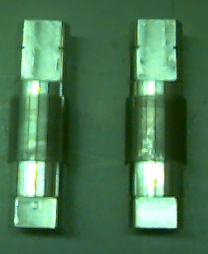
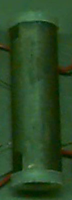
Shaft-Type Sensor (plastic caps on ends) |
|
|
|
Magnetoelastic Research Group
Western Illinois University
Department of Physics
|
Group Leader |
Research Associates |
|
Collaborators |
In recent years, a new application of magneto-elastic materials has arisen that allows the torque on a shaft to be measured by means of a non-contact probe. For example, a magneto-elastic shaft can be used in an automotive power steering system or in an automotive transmission system. We have examined two different torque transducer configurations; the first configuration is known as the ring-type sensor. A magneto-elastic ring of maraging steel is pressed onto a non-magnetic shaft. As the shaft is torqued, the stress on the ring produces an axial component of magnetic field that is linearly dependent on the applied torque. The second configuration is known as the shaft-type sensor. In this case, the entire shaft is constructed of maraging steel with two regions in the center that are magnetized in opposite directions.
|
Ring-Type Sensor |
Shaft-Type Sensor (plastic caps on ends) |
|
|
|
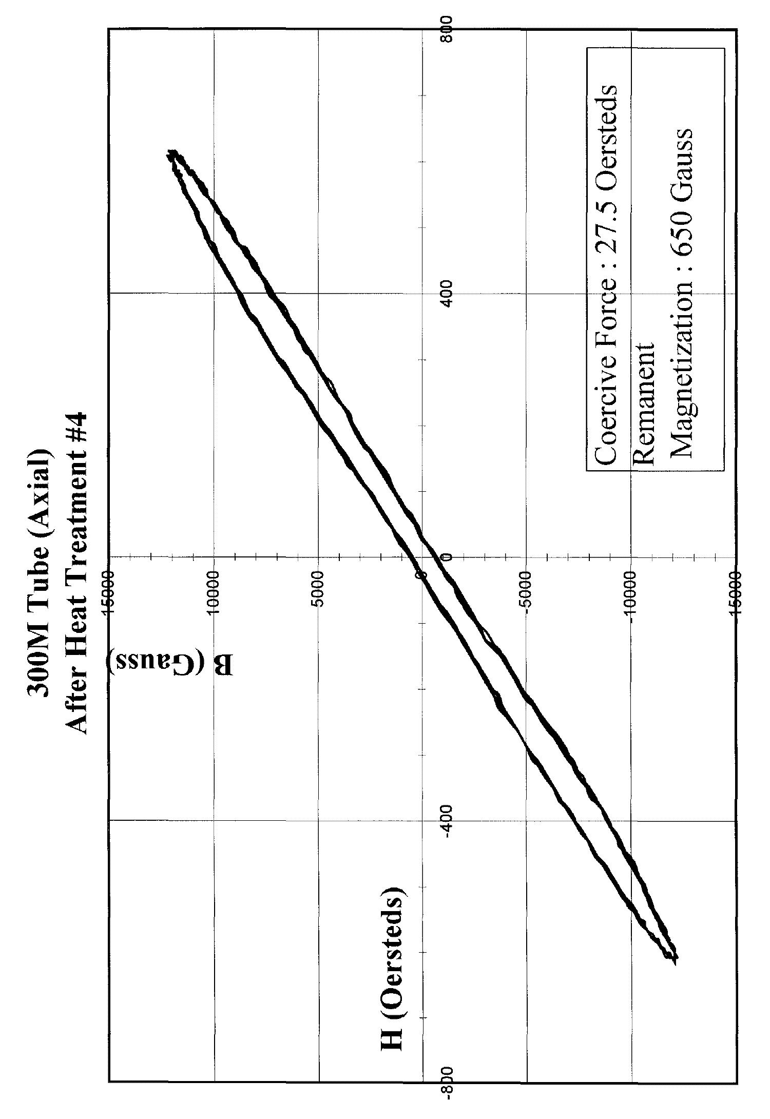
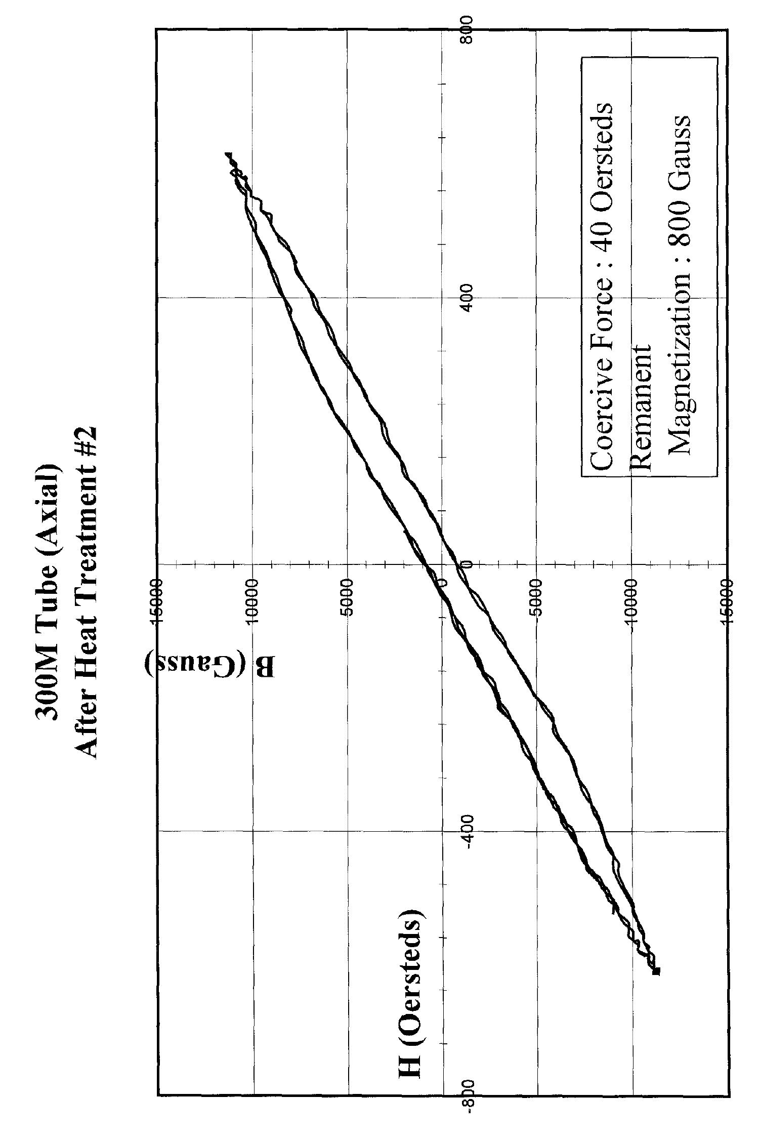
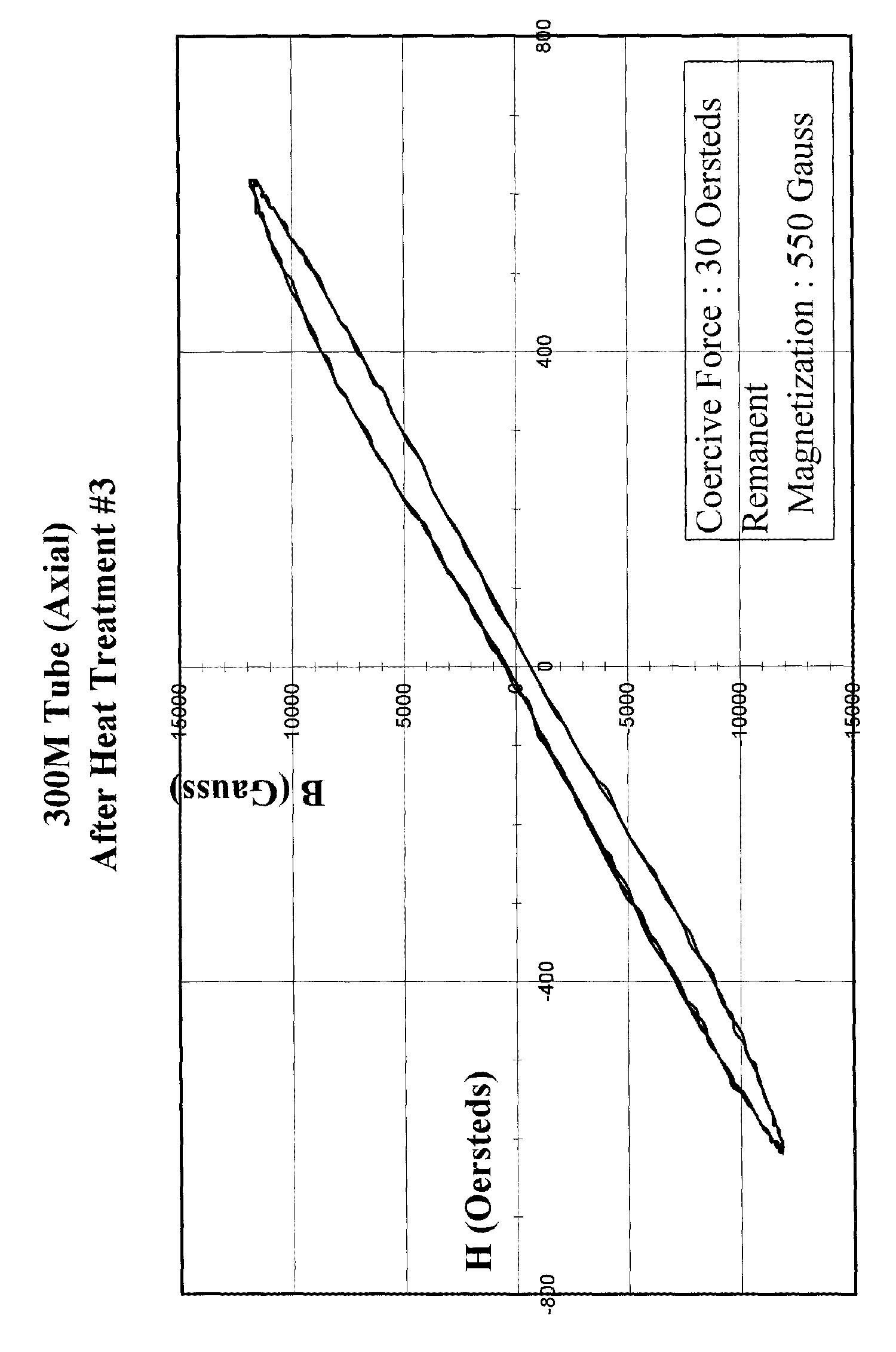
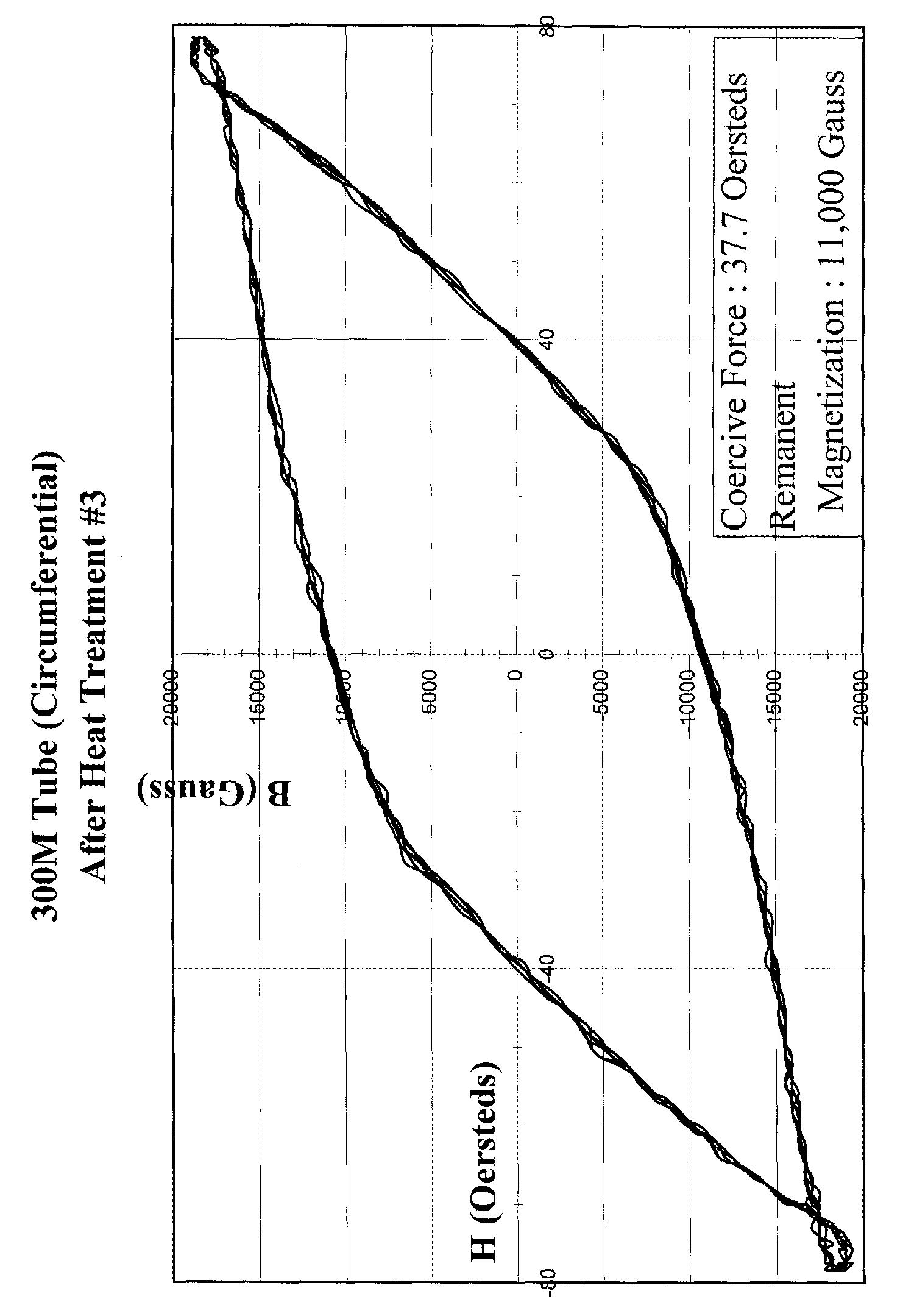
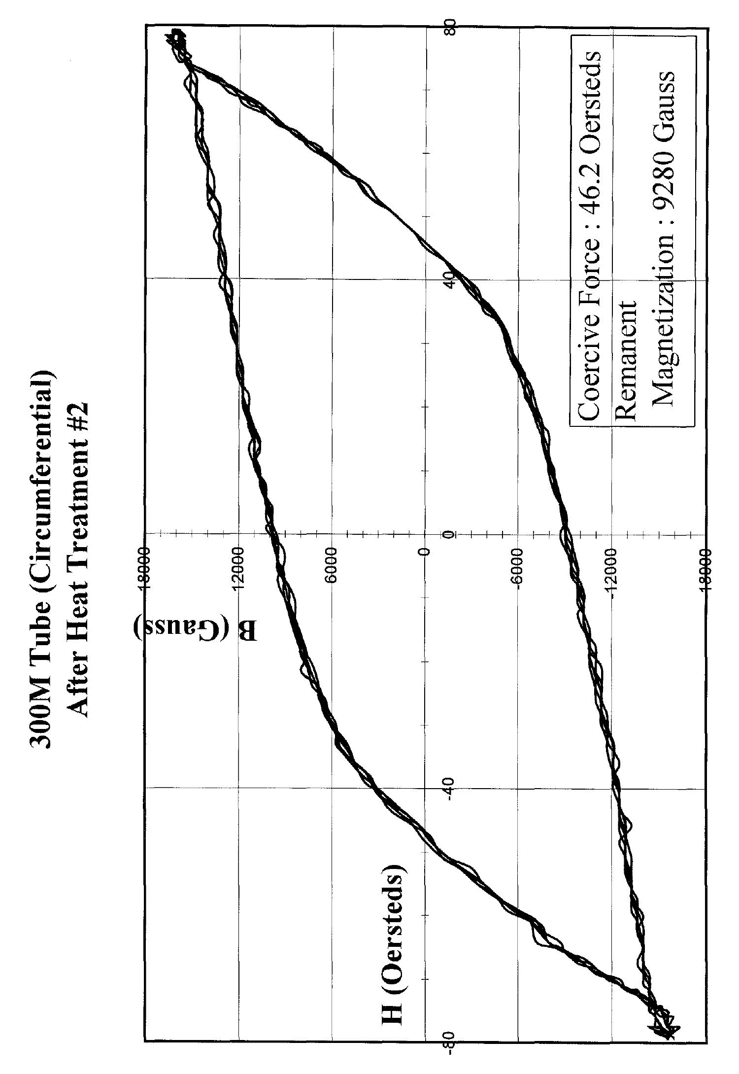
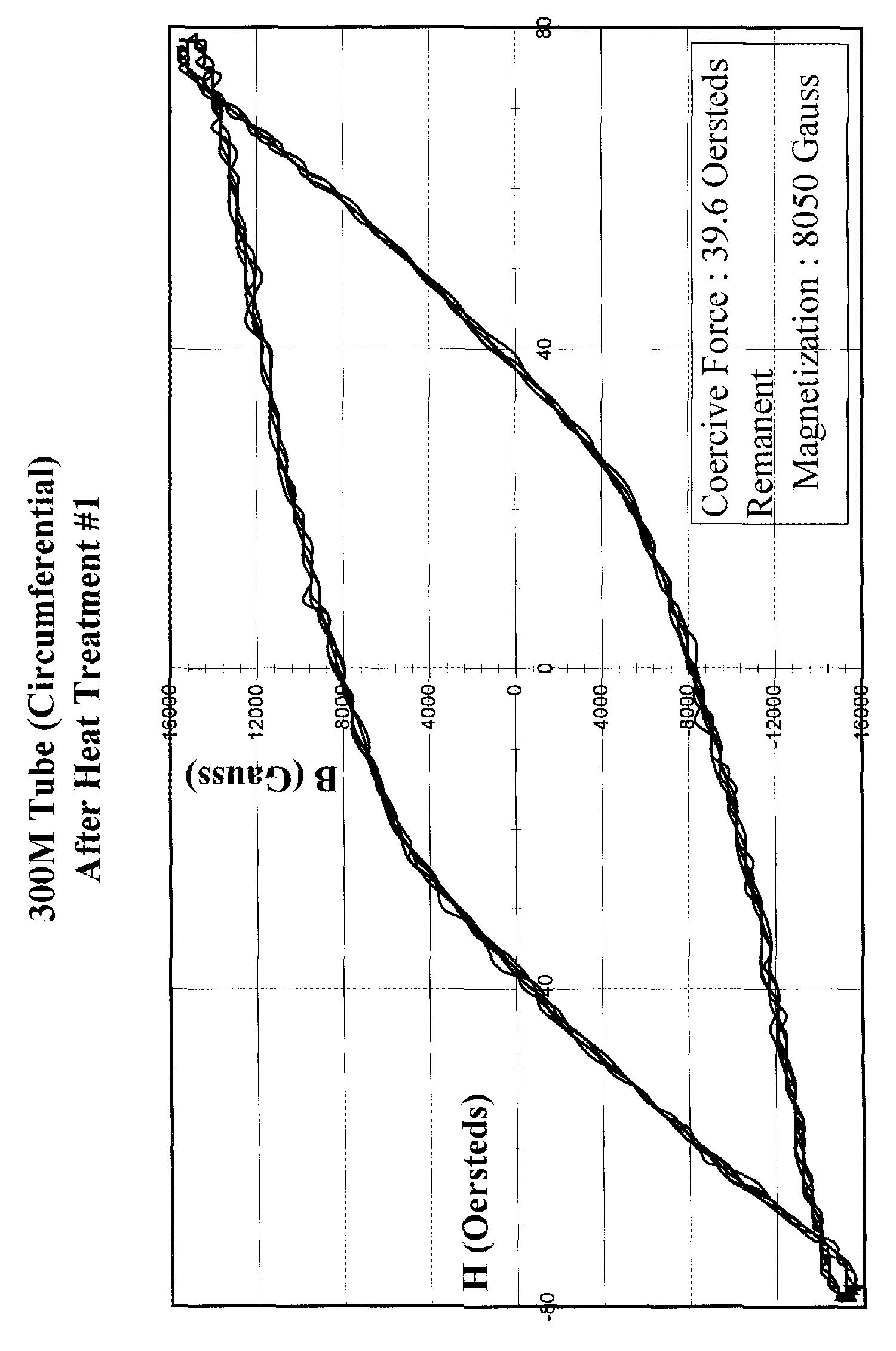
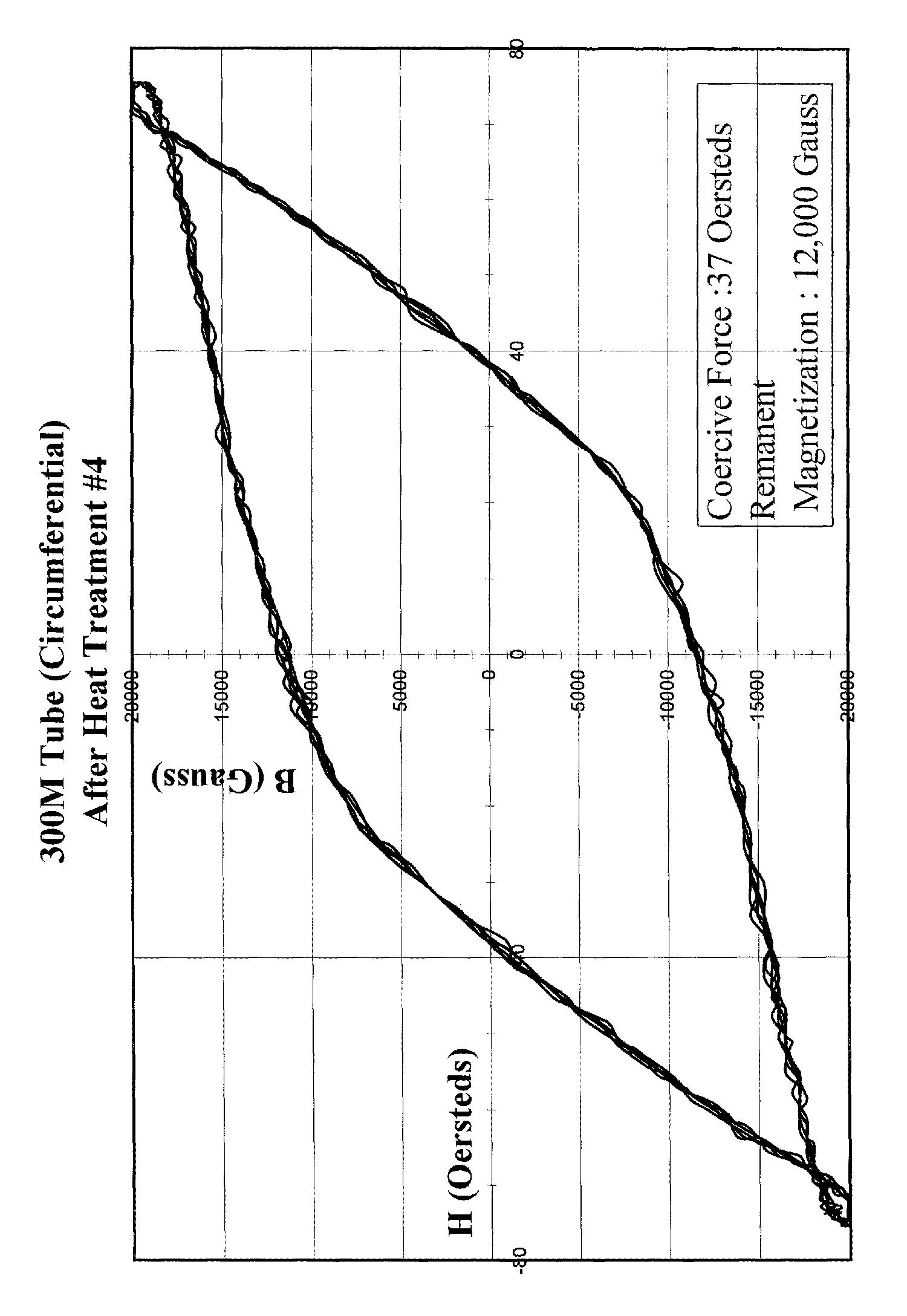
A high amount of retentivity and coercive force is needed in the circumferential direction to maintain the original magnetization of the sensory region. However, low amounts of retentivity and coercive force are required in the axial direction to allow for maximum sensitivity of the sensory region. Therefore, we have measured the hysteresis of the axial and circumferential magnetic fields to determine the characteristics of the shaft-type sensor. A heat-treatment process was then developed and by examining the hysteresis characteristics after each step, we have found significant improvement in the transducer reliability as a torque-sensing device subsequent to the heat-treatment process.
|
After Heat Treatment 1 |
After Heat Treatment 2 |
After Heat Treatment 3 |
After Heat Treatment 4 |
 |
 |
 |
 |
 |
 |
 |
 |
First, they were baked at 925 degrees Celsius for two hours in a helium atmosphere and then cooled. Second, they were baked at 875 degrees Celsius for two hours in a helium atmosphere and then quenched in motor oil. Third, they were baked at 300 degrees Celsius for four hours in an atmosphere of air and then cooled. Finally, the third step was repeated to complete the heat-treatment process by a double annealing.
Effects of Heat-Treatment on Sensitivity
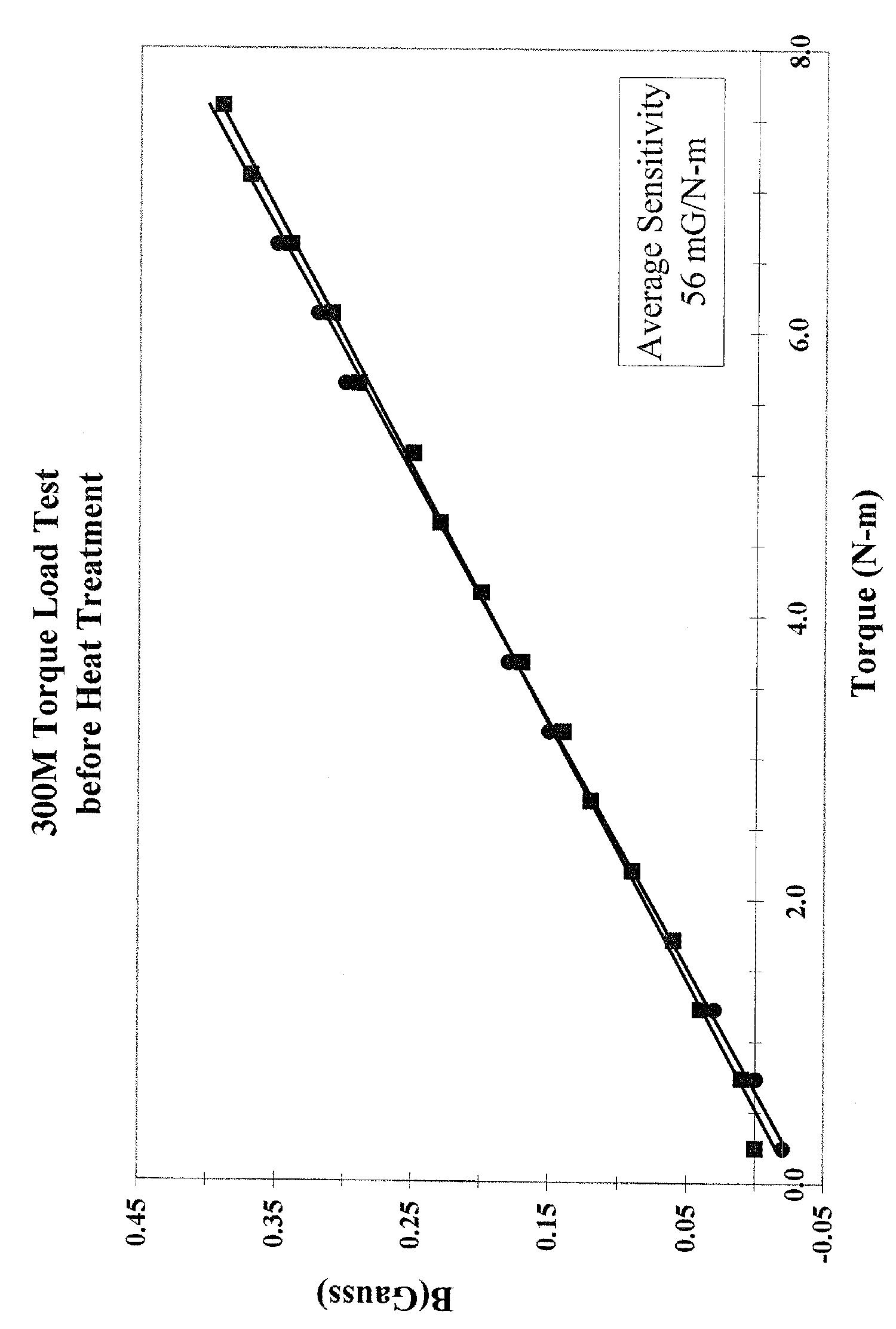
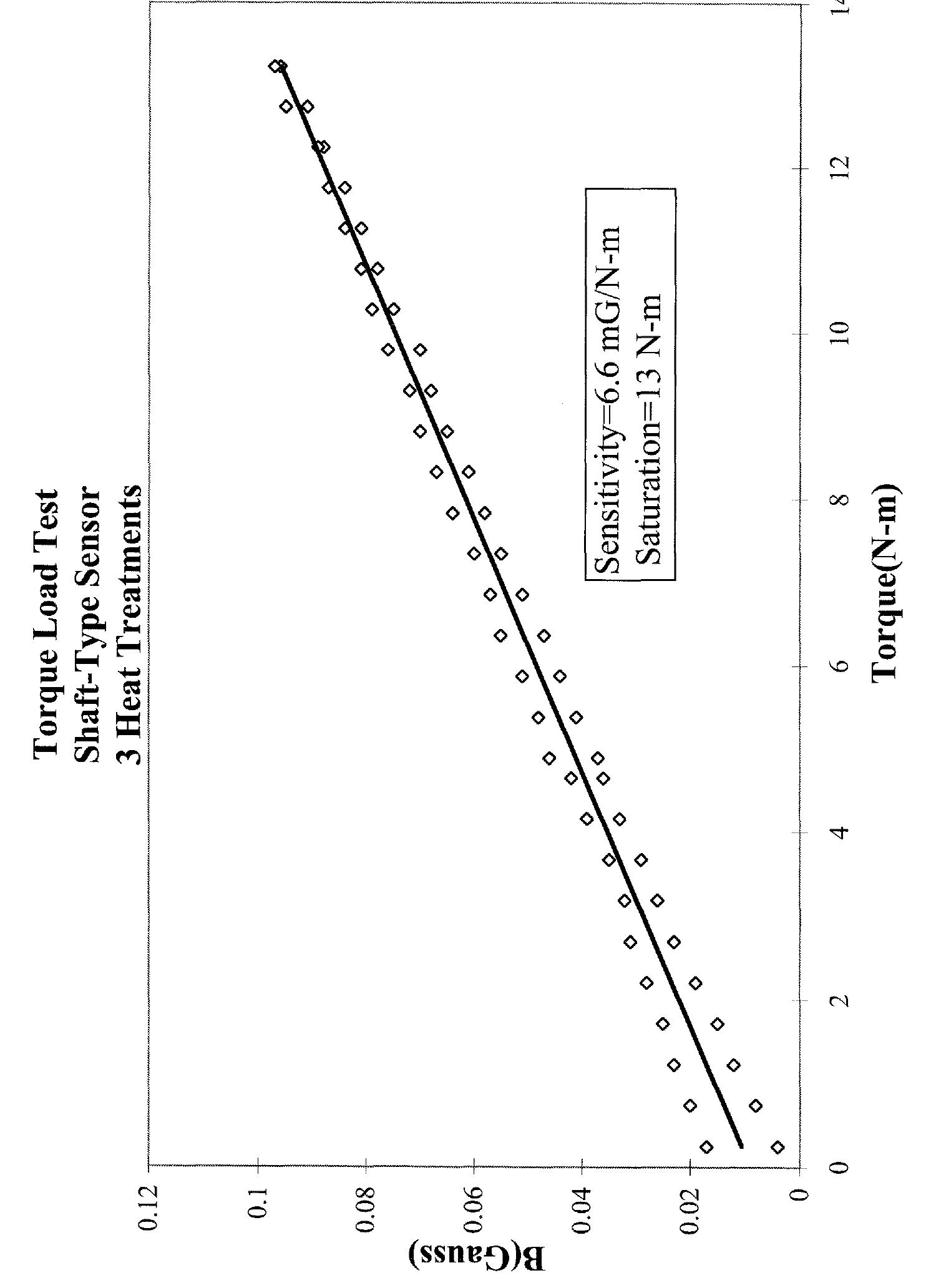
The sensitivity of the shaft is defined as the change in measured field strength in milli-Gauss per Newton-meter of applied torque. Before and after each step of the heat-treatment process, a sensitivity map was carried out on the shaft to evaluate its sensitivity. Of course, as the sensitivity increases, the sensor's usefulness in applications increases as well. In addition, the shaft displays a linear field dependence on torque until a certain saturation limit is met. When this saturation limit is exceeded, the shaft no longer returns to a zero-magnetic field value in the absence of an applied torque. Therefore, it was necessary to determine the saturation limit in each case.
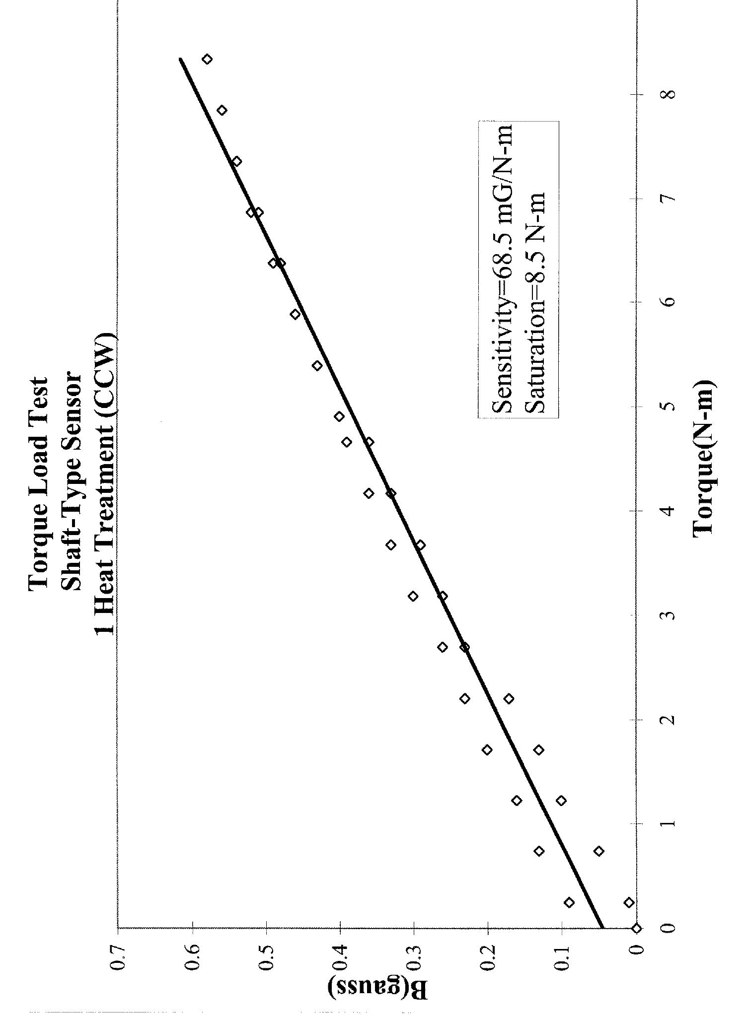
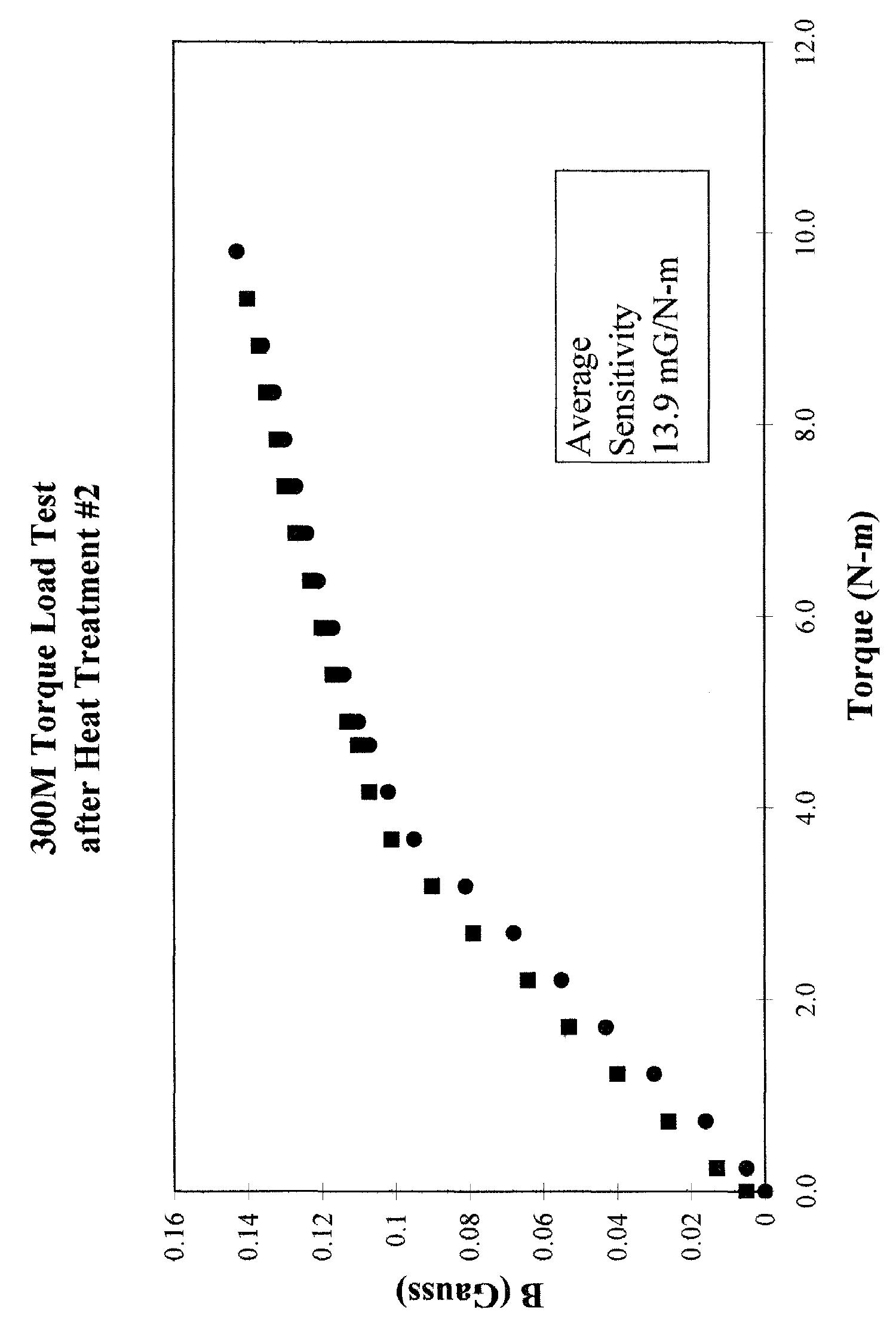
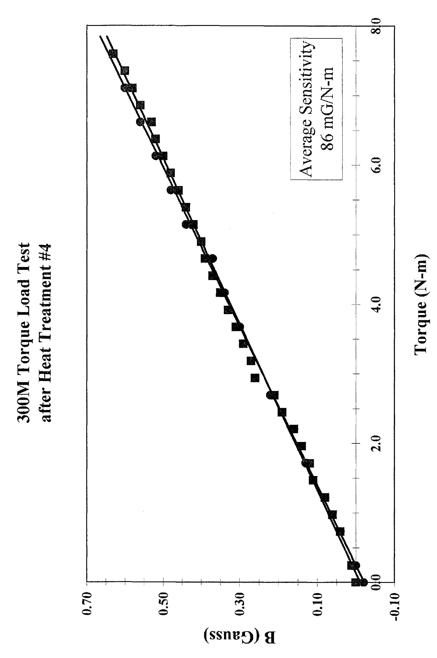
Initially, the shaft displayed a reasonably linear response with a sensitivity value of 56 mG/N-m. It was able to withstand a torque of approximately 8 N-m while maintaining its linear response, as can be seen here. After the first step of the heat-treatment process, seen here the response was not as linear as in the first case. However, sensitivity significantly increased to 68.5 mG/N-m and the saturation limit increased slightly to 8.5 N-m. The results of the second step of the heat-treatment process can be seen here. The response was very linear but only to a very low saturation limit of approximately 4 N-m. Sensitivity decreased dramatically as well, to 13.9 mG/N-m. Step 3 of the heat-treatment process provided some dramatic results as well, as can be seen here. Saturation rose sharply to 13 N-m while sensitivity dropped even further to 6.6 mG/N-m. The response remained linear however. Finally, step 4 of the heat-treatment process, seen here provided the desired results of a high sensitivity at 86 mG/N-m and a reasonable saturation limit of approximately 8 N-m while maintaining a linear response.
Each plot contains two sets of data. The first set represents the "upstroke" or the addition of torque. The second set represents the "downstroke" or decrease of torque. These values should be as close to each other as possible if the sensor is to perform reliably.
Production of a Torque Sensor
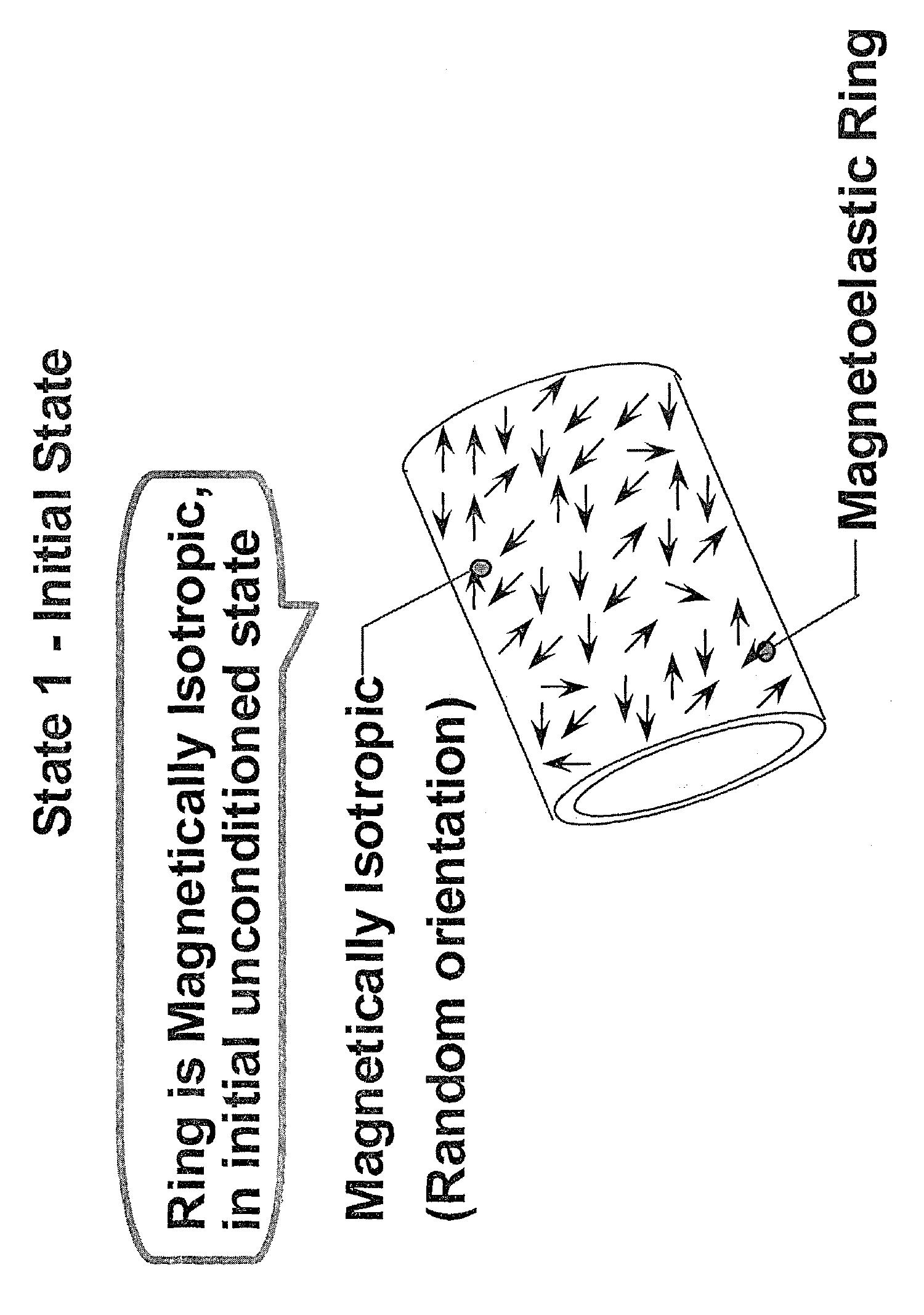
The process of producing the shaft-type sensor is identical to that of the ring-type with the exception of the step of pressing the ring onto the shaft to produce a uniaxial anisotropy, which is omitted in the shaft-type construction process. In the shaft-type sensor, the hollow cylindrical symmetry of the shaft maintains the circumferential easy magnetization axis even without the hoop stress, which was available for its maintenance in the ring-type sensor. The maraging steel is magnetically isotropic when it is first formed into a ring. This means that the magnetic dipoles are randomly oriented throughout the material in every direction, as seen in the first panel diagram. The ring is then pressed onto the shaft, which results in a uniaxial anisotropy. This means that the dipoles will very easily now align in an alternating pattern of clockwise and counter-clockwise directions.
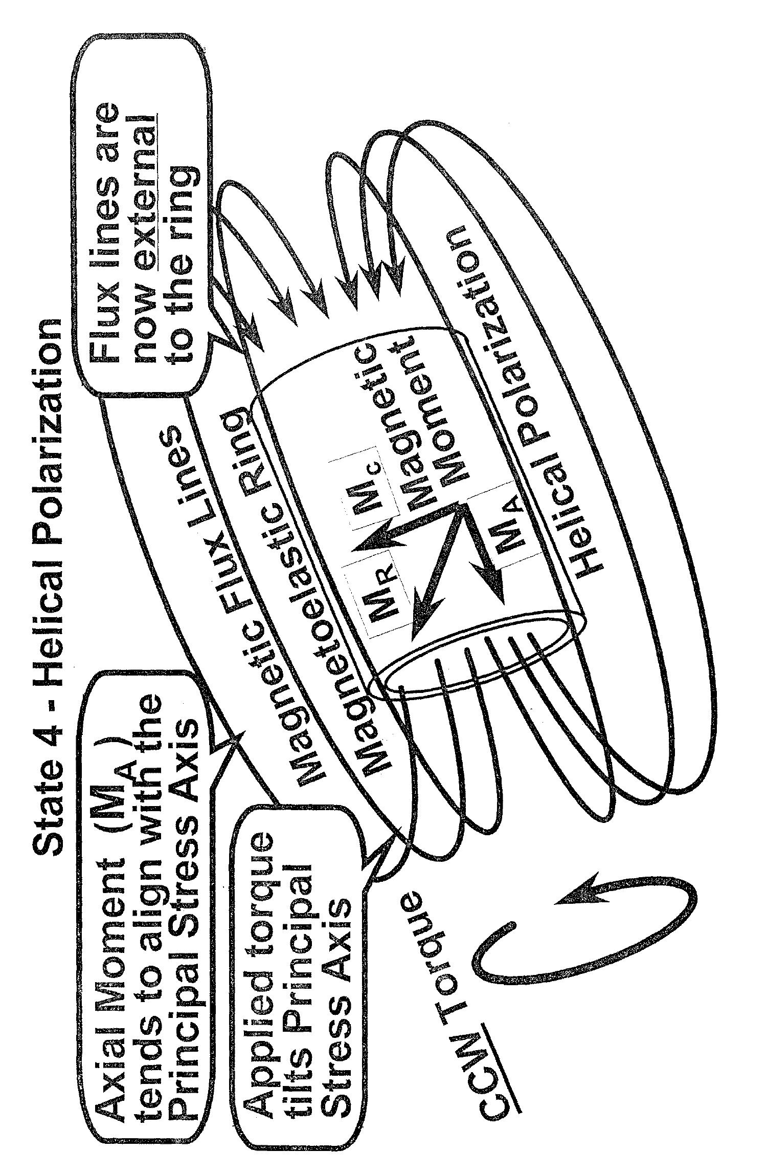
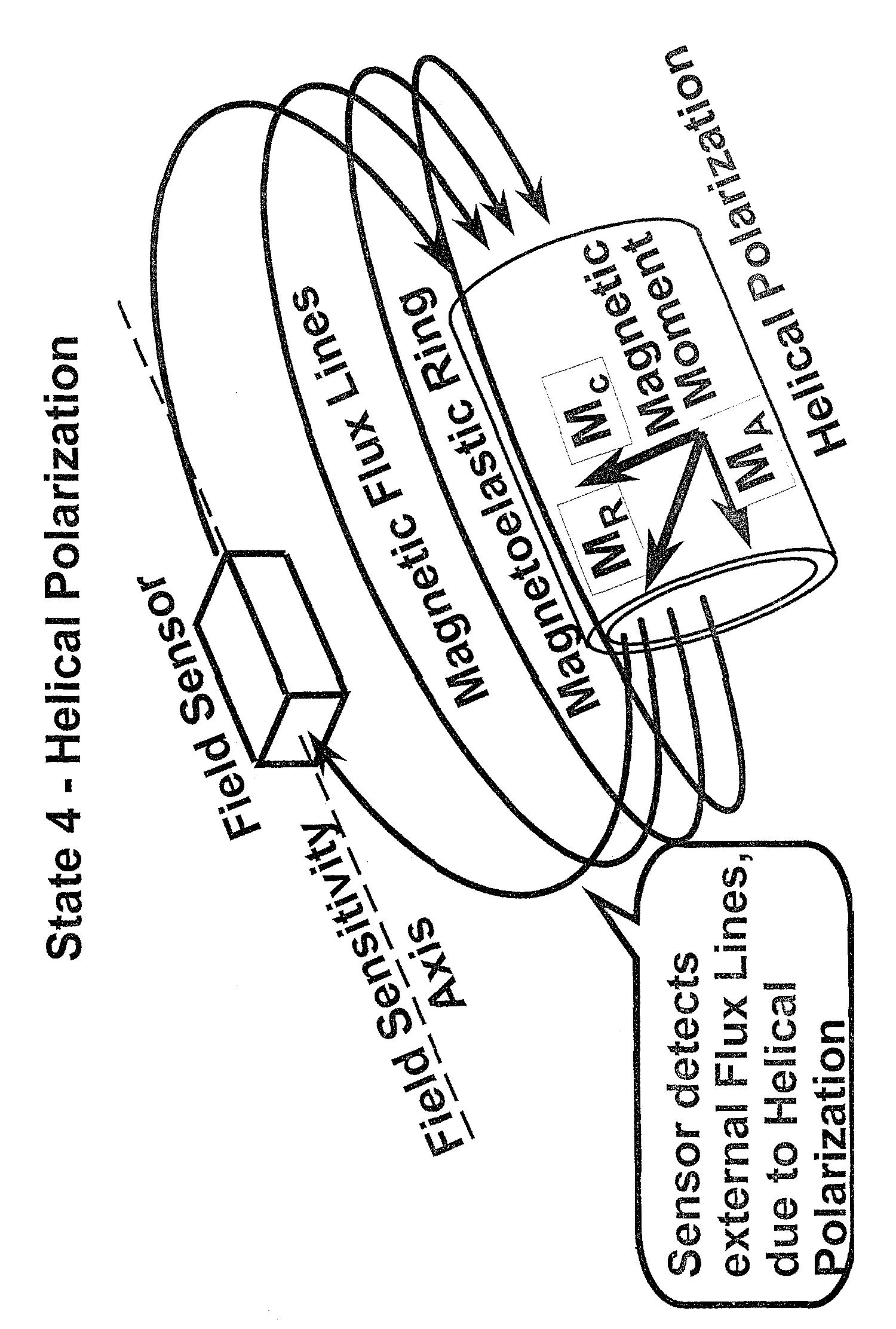
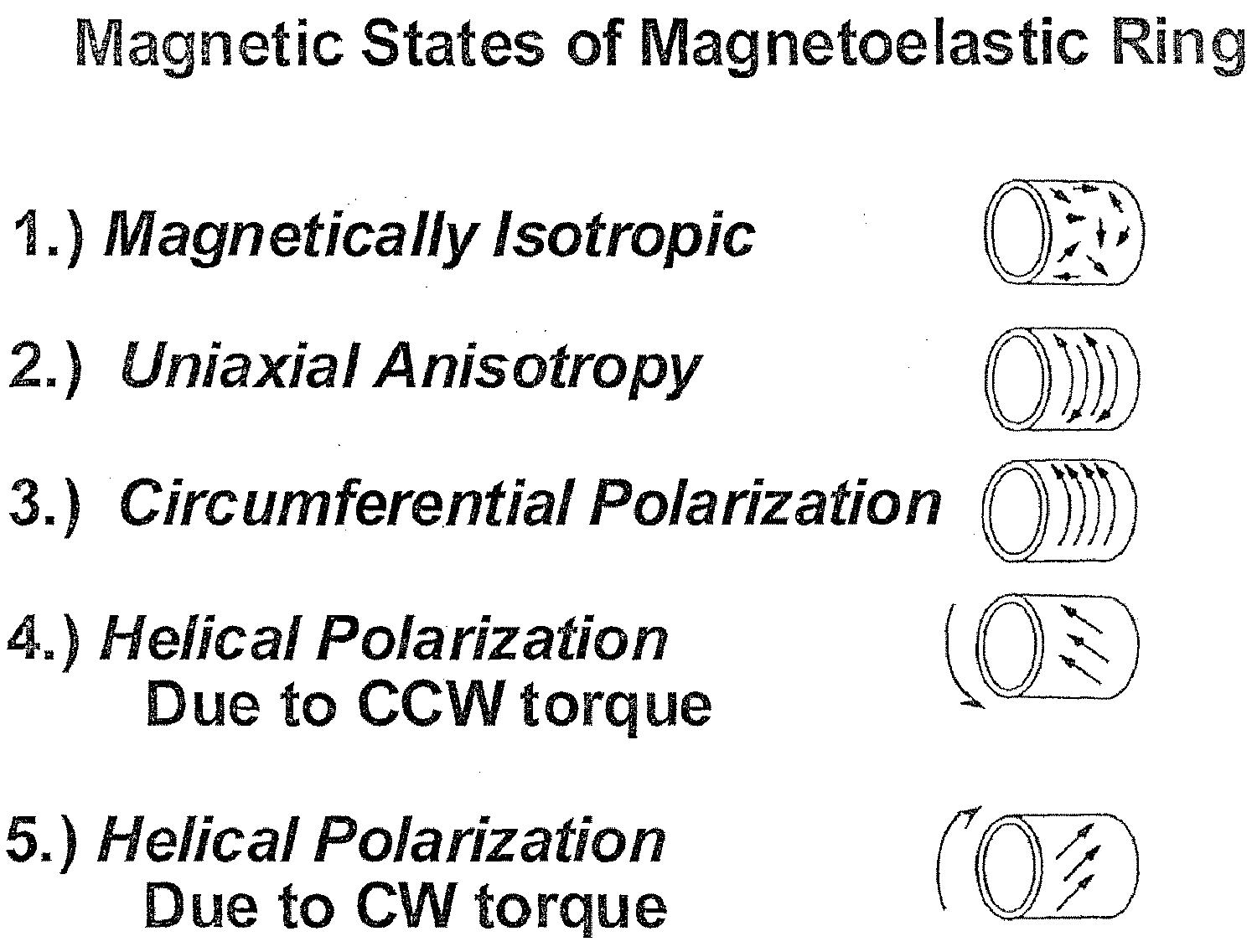
The ring is spin magnetized with (a) flat pole permanent magnet(s) to induce a circumferential polarization in one or two unidirectional segments, as seen in the second panel diagram. When a torque is applied to the ring, the circumferential field takes on a helical orientation. The applied torque tilts the principal stress axis. The axial component of the field then aligns with the principal stress axis and magnetic flux lines are now external to the ring as seen in the third panel diagram. A field sensor can now be used to measure the magnitude of the external flux lines due to the helical polarization, as seen in the fourth panel diagram.
Of course, stray fields due to the earth or other external sources could alter the value measured by the sensor. Magnetizing two regions of the ring in opposing directions circumvents this problem. This is helpful for two reasons. First, the resultant helical polarization signal is twice as strong so the shaft is more sensitive. Second, a system of differential electronics can be used to sense in two directions so any stray signals will be disregarded. The last panel diagramsummarizes the states of magnetoelastic torque sensors.